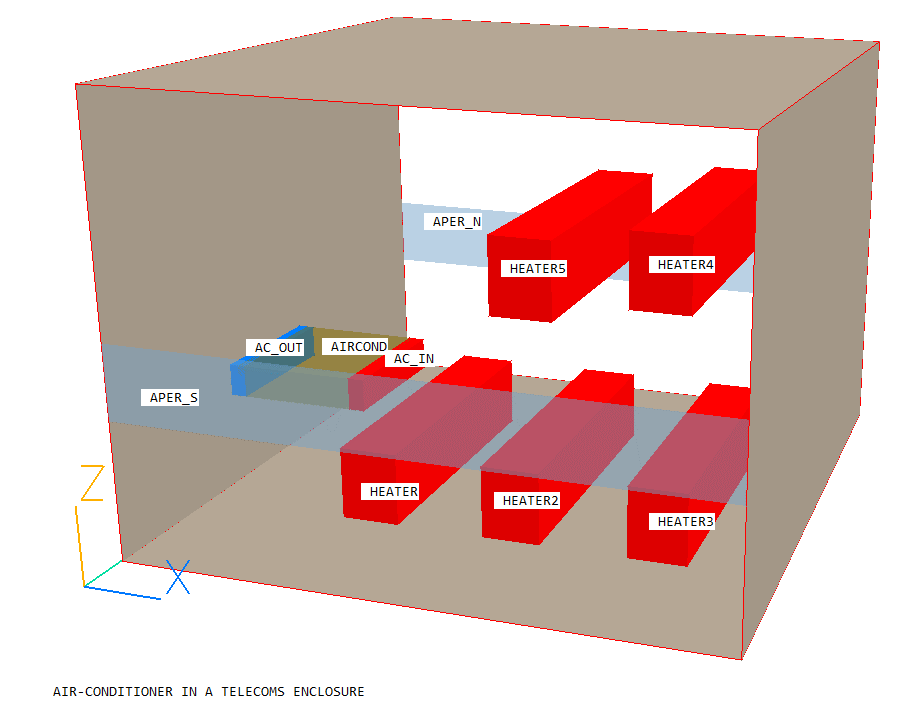
The following instructions will allow the user to set up and run the simulation of an air-conditioner in a telecom enclosure in VR. The enclosure contains heat dissipating equipment and an air-conditioner which removes heat. The case demonstrates the use of linked anlged-ins to model an air-conditioning unit.
The flow is three-dimensional, turbulent and weakly compressible, and its geometry is shown below.

Buoyancy effects are significant due to the localised heating of the air around the equipment.
The geometry and simulation options are set up using VR Editor, the calculations are performed using the PHOENICS solver, EARTH, and the results are viewed using VR Viewer. Velocity, pressure and temperature will be simulated. This simulation will be run in parallel.
From the system level:
To enter the PHOENICS-VR environment, click on the PHOENICS icon on the desktop, or click on Start, programs, PHOENICS, PHOENICS.
In PHOENICS-VR environment,
Start with an 'empty' case - click on 'File' then on 'Start New Case', then select 'Core'. Then click on 'OK' to confirm the resetting.
To enter VR Editor:
This is the default mode of operation.
Set the title and domain size, activate solution of variables and select solver:
Click on 'Main Menu' and set 'Air-Conditioner in a Telecom Enclosure' as the Title.
Click on 'Geometry'.
Change the X-Domain Size to 4 m.
Change the Y-Domain Size to 4 m.
Change the Z-Domain Size to 3 m.
Click 'OK' to close the Grid mesh settings dialogue.
Click on 'Models'.
Leave the 'Solution for velocities and pressure' ON.
Click on 'Energy Equation' and select 'Temperature' as energy formulation. This will show as 'TOTAL' which is correct for this simulation.
For this simulation the standard k-ε model is used. To set this, click on 'Chen-Kim KE' next to 'Turbulence models'. Select 'KE variants'. Click 'OK', then select 'Standard KE'.
Click 'OK' to confirm the setting.
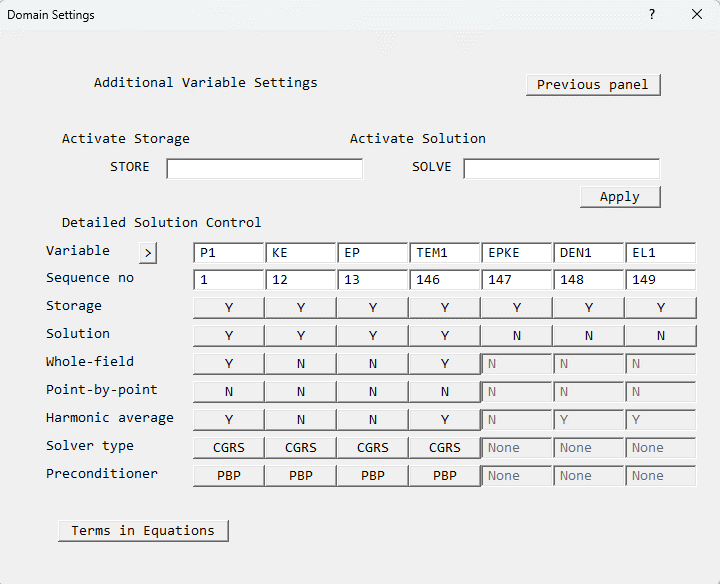
Click on 'settings' next to 'Solution control / Extra variables'.
Click on 'Stone' next to 'Solver type' in the 'P1' column, and select 'CGRS'. This will select the CGRS solver for all variables. After clicking 'OK', the dialogue should look like this:
Click 'Previous panel' to return to the main menu.
Click 'Properties'. Select '2 Air using Ideal gas Law, STP' as the domain material (it is in the Gases section).
Set the ambient temperature to 100 degrees.
Click 'Sources', and turn Gravitational forces ON. The Density_difference method will be automatically selected, and the Reference density will be automatically set from the ambient temperature and pressure on the Properties panel.
Gravity acts in the -Z direction, so make sure the X and Y components are set to 0,0 and the Z component is -9.81.
Click on 'Top Menu' to return to the top level of the main menu.
Create the internal surfaces of the domain:
Click on 'Domain Faces'.
Set 'Wall' to 'Yes' for the Xmin, Xmax, Zmin and Zmax faces.
Click on 'OK' to close the Domain Faces Dialogue Box, and 'OK' again to close the reminder to set / check boundary conditions.
Click on 'OK' to exit the Main Menu.
If required, to re-scale the view to fit the geometry, click 'Reset' on the Movement control panel, then 'Fit to window', or select 'Fit to window' in the drop-down menu next to
on the toolbar.
Create the objects making up the scene
Click on the 'Object Management' button (O on the toolbar or
on the hand set). This will display a list of objects. The current objects are the domain boundary plates.
Select all the PLATE objects, right-click and 'Hide objects'. This will prevent the plates from obscuring the inside of the domain.
Create the air-conditioning unit:
Click on 'Object', 'New', 'New object', 'Blockage'.
Change name to AIRCOND.
Click on 'Size' to set the SIZE of object as:
Xsize: 0.8
Ysize: 0.85
Zsize: 0.2
Click on 'Place' to set the Position of object as:
Xpos: 0.595
Ypos: 0.5
Zpos: 1.0
To change the colour of the object for clarity, click on 'Options'.
Select 'Palette index' and put 118 in the value box. Change the 'Opaqueness' value to 50.
Click on 'OK' to exit the Object Dialogue Box. AIRCOND will now appear in the Object Management list of objects.
Create the air-conditioner intake:
Click on 'Object', 'New', 'New object', 'Angled-in'.
Change name to AC_IN.
Click on 'Size' to set the SIZE of object as:
Xsize: 0.1
Ysize: 0.85
Zsize: 0.2
Click on 'Place' to set the Position of object as:
Xpos: 1.3555
Ypos: 0.5
Zpos: 1.0
Note that the shape and size of the angled-in object do not really matter - what matters is the size and shape of the area of intersection between it and any blockage which it overlaps. In this case the active inlet area will be the outer surface of the AIRCOND object which lies within AC_IN.
Click on 'General'.
Click on 'Attributes' to set the inlet condition.
Enter -2.9 m/s for the velocity in the X-direction. This is pointing into the AIRCOND blockage and so will be treated as an extraction rate. In this case, the settings for temperature and turbulence do not matter, as it is the in-cell values which will be convected out. Click 'OK' to close the Attributes dialogue.
To change the colour of the object for clarity, click on 'Options'.
Select 'Palette index' and put 15 in the value box. Change the 'Opaqueness' value to 100.
Click on 'OK' to close the Object Specification Dialogue Box.
Create the air-conditioner outlet:
Click on 'Object', 'New', 'New Object', 'Angled-in'.
Change name to AC_OUT.
Click on 'Size' and set SIZE of object as:
Xsize: 0.1
Ysize: 0.85
Zsize: 0.2
Click on 'Place' to set the Position of object as:
Xpos: 0.54
Ypos: 0.5
Zpos: 1.0
Note that the shape and size of the angled-in object do not really matter - what matters is the size and shape of the area of intersection between it and any blockage which it overlaps. In this case the active outlet area will be the outer surface of the AIRCOND object which lies within AC_OUT.
Click on 'General'.
Click on 'Attributes' to set the inlet condition. We want to link the outflow here to the inflow calculated for AC_IN. AC_IN is the preceding Angled-in in the list. Click on 'Link to other ANGLED-IN' until it states 'Previous'.
Set the additional heat source to -10500W. This is the heat removed by the air-conditioning unit.
Click 'OK' to close the Attributes dialogue.
To change the colour of the object for clarity, click on 'Options'.
Select 'Palette index' and put 3 in the value box. Change the 'Opaqueness' value to 100.
Click on 'OK' to close the Object Specification Dialogue Box.
Create the south (low-y) outlet:
Click on 'Object', 'New', 'New object', 'Outlet' and select the Y plane for the outlet to lie in.
Change name to APER_S.
Click on 'Size' to set the SIZE of object as:
Xsize: 4.0
Ysize: 0.0
Zsize: 0.5
Click on 'Place' to set the Position of object as:
Xpos: 0.0
Ypos: 0.0
Zpos: 0.94
Click on 'General' then 'Attributes'.
Change the 'Coefficient' to 1. A lower coefficient allows more flexibility in the boundary condition, that is, the internal pressure at APER_S is less strongly tied to the external pressure than with a higher coefficient.
Click on 'User set' next to 'Velocity Y' to change it to 'In-cell'
Click on 'OK' to close the Attributes dialogue.
Click on 'OK' to close the Object Dialogue Box.
Create the north (high-y) outlet:
Click on 'Object', 'New', 'New object', 'Outlet' and select the Y plane for the outlet to lie in.
Change name to APER_N.
Click on 'Size' to set the SIZE of object as:
Xsize: 4.0
Ysize: 0.0
Zsize: 0.5
Click on 'Place' to set the Position of object as:
Xpos: 0.0
Ypos: 4.0
Zpos: 0.94
Click on 'General' then 'Attributes'.
Change the 'Coefficient' to 1, and the value of 'Velocity Y' to 3m/s.
Click on 'OK' to close the Attributes dialogue.
Click on 'OK' to close the Object Dialogue Box.
Create the first HEATER object:
In the Object management dialogue, click on 'Object', 'New' 'New Object', 'Blockage'.
Change name to HEATER.
Click on 'Size' to set the SIZE of object as:
Xsize: 0.4
Ysize: 2.0
Zsize: 0.5
Click on 'Place' to set the Position of object as:
Xpos: 0.995
Ypos: 1.0
Zpos: 0.0
Click on 'General'.
Click 'Attributes'. Click 'Types', then 'Solids' and select ALUMINIUM.
Click 'Energy Source', and select 'Fixed Heat Flux'. Enter 2000 in the Value box to set a heat source of 2000W for the entire object.
Click on 'OK' to close the Attributes dialogue.
Click 'OK' to close the Object Specification Dialogue Box.
Create the remaining HEATER objects:
Check that the HEATER object is still selected and appears with white contours, if not select it from the list in the Object Management Dialogue.
Now click on the 'Duplicate object or group' button, or select 'Object', 'Copy Object(s)' from the Object Management Dialogue menu bar. This will create a new object named HEATE_11 with the same attributes as the HEATER object.
Select the new object from the Object Management Dialogue.
Change name to HEATER2.
Click on 'Place' to set the Position of object as:
Xpos: 2.0
Ypos: 1.0
Zpos: 0.0
Click 'OK' to close the Object Specification Dialogue Box.
Repeat the steps to duplicate the object a further 3 times. There will be 5 objects with the same size and attributes, named HEATER, HEATER2, HEATE_12, HEATE_13 and HEATE_14. Update the remaining three as follows:
Select the object HEATE_12 from the Object Management Dialogue.
Change name to HEATER3.
Click on 'Place' to set the Position of object as:
Xpos: 3.0
Ypos: 1.0
Zpos: 0.0
Click 'OK' to close the Object Specification Dialogue Box.
Select the object HEATE_13 from the Object Management Dialogue.
Change name to HEATER4.
Click on 'Place' to set the Position of object as:
Xpos: 3.0
Ypos: 1.0
Zpos: 1.66
Click 'OK' to close the Object Specification Dialogue Box.
Select the object HEATE_14 from the Object Management Dialogue.
Change name to HEATER5
Click on 'Place' to set the Position of object as:
Xpos: 2.25
Ypos: 0.61
Zpos: 1.66
Click 'OK' to close the Object Specification Dialogue Box.
Set the grid:
Click on the 'Mesh toggle' button. The default mesh will appear on the screen. The orange lines are region lines, and denote the edges of the bounding boxes of each object. The blue lines are ordinary grid lines introduced by the auto-mesher.
The auto-mesher gives a mesh of 75 cells in X, 60 in Y and 63 in Z. This is too fine for the purposes of the tutorial, as the case would take too long to run.
For now, we will coarsen the grid in all 3 directions.
Right-click anywhere on the image, and the 'Auto meshing' dialogue box will appear. Moving the slider to the left will increase the number of cells, moving it to the right will decrease the number of cells.
Select the X direction. Move the slider to the right until there are 48 cells shown in X. This will happen when the 'Minimum cell fraction' is around 1.7%.
Select the Z direction. Move the slider to the right until there are 38 cells shown in Z. This will happen when the 'Minimum cell fraction' is around 1.9%.
Select the Y direction, and change the view slightly so that the Y grid becomes visible. Move the slider to the right until there are 35 cells shown in Y. This will happen when the 'Minimum cell fraction' is around 1.9%.
Click 'OK' to close the Auto meshing dialogue.
The final mesh should look like this:
Click the mesh toggle to hide the mesh display.
Set remaining solution control parameters:
In the Main Menu, click on 'Numerics'.
Set the number of iterations to 2000. This is still not enough for a fully-converged solution, but will give a good idea of the flow.
Click on 'Relaxation control'.
Click 'ON' next to 'Automatic Convergence Control' and click 'OK' to set it as 'OFF'. This turns off CONWIZ, the automatic convergence wizard, and allows manual adjustment of the relaxation parameters. For more information on convergence and relaxation, see the convergence entry in POLIS.
Set the 'Factor' for U1, V1 and W1 to 0.01; KE and EP to 0.3; and TEM1 to 1. These settings are sufficient to prevent the solution from diverging.
Click 'Previous panel' to return to the 'Numerics' page.
Click 'Iteration control'.
Set LITER for KE and EP to 40, and for TEM1 to 100. Use the arrows next to 'Variable' to scroll through the variables.
Click 'Previous Panel' to return to the 'Numerics' page.
Click on 'Top menu' to return to the top menu.
Click on 'OK' to exit the Main Menu.
Setting the Probe Location
Before running the solver, it is a good idea to place the probe in a suitable place to monitor the convergence of the solution. Too close to an inlet, and the value will settle down very quickly before the rest of the solution. Placed in a recirculation zone, it may still show traces of change even though the bulk solution is converged. In this case, between the air-conditioner output and the wall is fine.
Click on the probe icon
on the toolbar or double-click the probe itself, and move the probe to X=0.2, Y=0.85, Z=1.1
In the PHOENICS-VR environment, click on 'Run', 'Parallel Solver'. The default number of cores is 4. This can be increased to 8 if available. Click on 'OK', then 'OK' again to confirm running Earth.
In the PHOENICS-VR environment, click on 'Run', 'Post processor',then 'GUI - Post processor (VR Viewer)'. Click 'OK' on the file names dialogue to accept the default files.
To view:
To select the plotting variable:
To change the direction of the plotting plane, set the slice direction to X, Y or Z ![]()
To change the position of the plotting plane, move the probe using the probe position buttons:
 .
.
Alternatively, click on the probe icon ![]() on the toolbar or double-click the probe itself to bring up the Probe
Location dialogue.
on the toolbar or double-click the probe itself to bring up the Probe
Location dialogue.
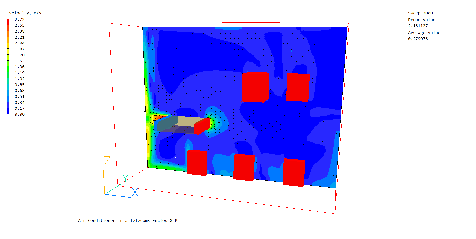
A typical vector and velocity plot from this case is:
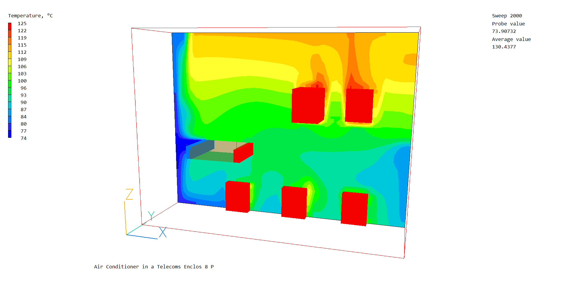
A typical temperature contour plot is:
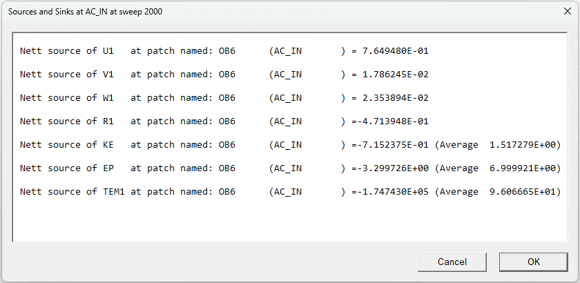
To check the temperatures and mass balance at AC_IN and AC_OUT, first select AC_IN then right-click and select 'Show Nett Sources'. The Satellite command prompt will open showing the sums of sources for the AC_IN object.
Now do the same for AC_OUT.
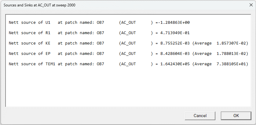
The mass flows (Nett source of R1, in kg/s) are equal and opposite, as expected. The energy sources (Nett source of TEM1 in W) are also opposite and the source at AC_OUT is 10500W lower, as expected. The average temperature (shown in brackets after 'Average') is lower at AC_OUT.
In the PHOENICS-VR environment, click on 'Save as a case', make a new folder called 'AIRCON' (e.g.) and save as 'CASE1' (e.g.).